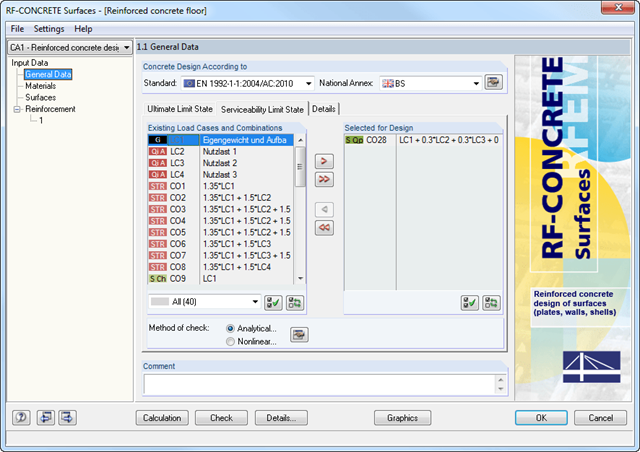
The material library already includes Swiss types of concrete and reinforcing steel available for design. However, you can always define other materials for the design according to SIA 262. The program performs the ultimate and the serviceability limit state design.
The crack width analysis can be performed using the design of Sigmas,adm, rebar spacing sL, or a direct calculation of crack widths according to the technical documentation D0182. Depending on the selected concrete type, the program determines the limit value Sigmas,adm according to D0182, Eq. 10.13; the upper limit is set by the design criterion fsd.
The calculation is performed successively for each load step. Permanent (plastic) deformations of previous load steps are considered when calculating further load steps. This way, it is also possible to perform a calculation with a structure relief.
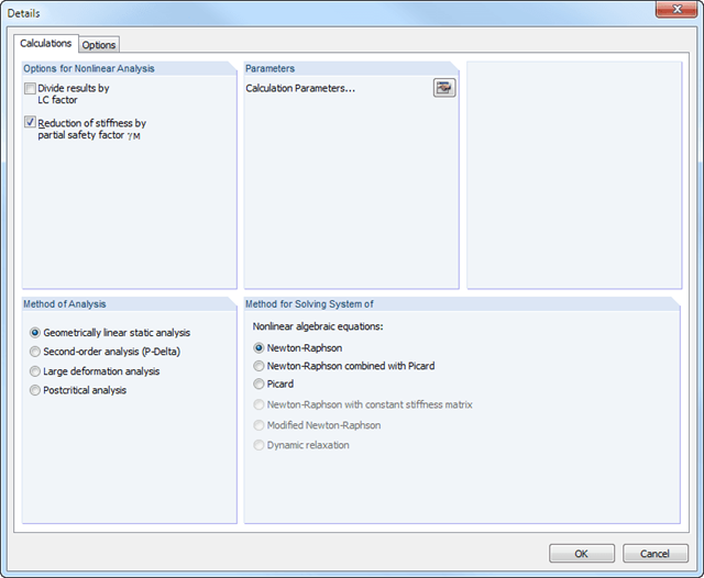
The loads of the individual steps are added up (depending on the signs) throughout the calculation process. You can freely select the method of analysis (linear static, second-order, large deformation, and postcritical analysis). Furthermore, the module manages the global calculation settings.
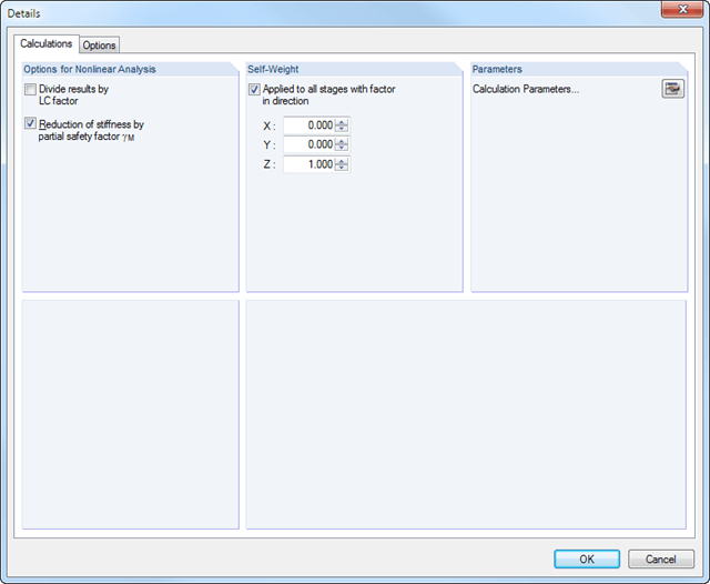
The calculation of the "Permanent Loads" is performed in compliance with the large deformation analysis successively for each construction stage.
The resulting geometry differences between the ideal and the deformed structural system from the previous construction stage are compared in the background. The next construction stage is built on top of the stressed system from the previous construction stage.
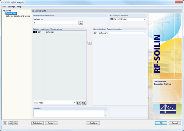
The definition of soil layers is performed in a clearly arranged input window. An extensible library facilitates the selection of soil properties.
The elasticity can be defined either by the stiffness modulus or the modulus of elasticity and the Poisson's ratio. It is possible to define any number of soil layers. You can assign the layers to the building graphically or by entering the relevant coordinates.
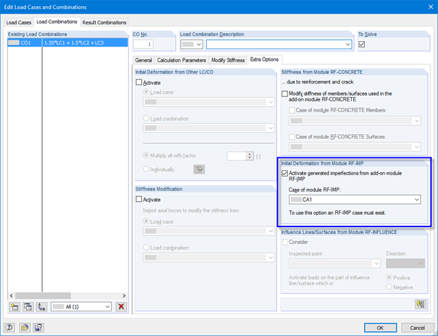
It is possible to use previously created pre-deformed FE mesh in load combinations. To do this, select the corresponding RF-IMP case in the calculation parameters of the load combination. Then, the calculation of internal forces is performed for the imperfect structure.
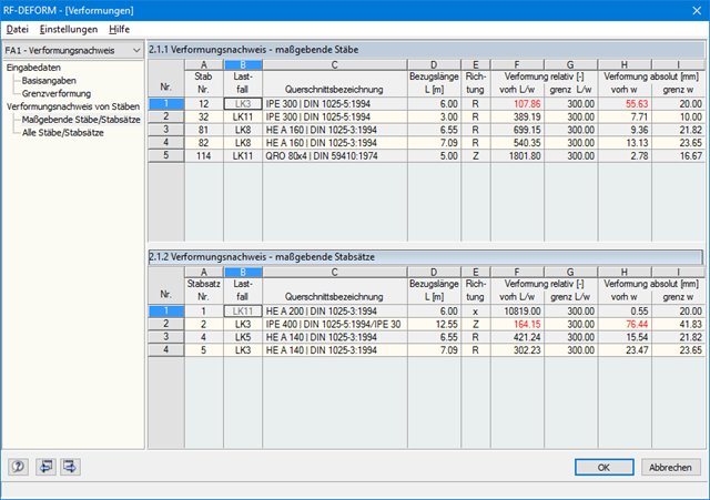
Relative and absolute deformations are compared to the respective limit values in clearly arranged tables. In this way, you can quickly evaluate the design results.
If the design for a member or member set fails, this is indicated in color. You can integrate the designs performed by RF-/DEFORM into the printout report in the same way as the RFEM/RSTAB data.
Design-relevant data are entered in two separate windows. Since the RF-/DEFORM module is very clearly arranged, working in it is very easy.
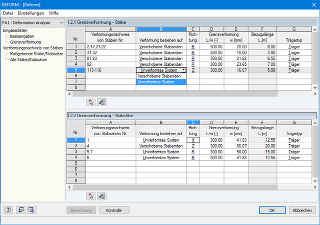
First of all, it is necessary to define the actions to be designed. Then, you can select the members and sets of members manually or graphically and assign the respective allowable limit deformations.
The deformations correspond to deformed member ends or an undeformed system.
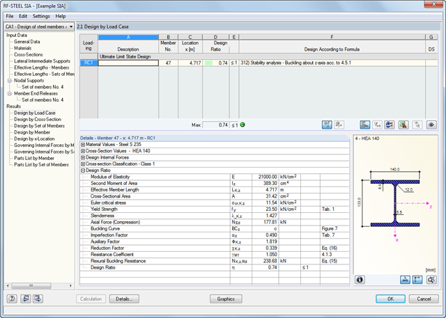
For reasons of result evaluation, clearly arranged result tables are available. The first window shows the maximum design ratios including the corresponding design of each designed load case, load combination, or result combination.
The other result windows list all detailed results sorted by specific subject in extendable tree menus. All intermediate results along the members can be displayed at any location. In this way, you can easily retrace how the module has performed the individual designs.
The complete module data are part of the RFEM/RSTAB printout report. You can select the report contents and extent specifically for the individual designs. The graphical result display of the governing design criteria in RFEM/RSTAB provides a quick overview of the design ratios of individual structural components.
The program creates a reinforcement proposal for the top and the bottom plate reinforcement. The program searches automatically for the most favorable reinforcement combination, with a mat and added rebars. If required, the rebars are distributed across two reinforcement areas by curtailment. It is possible to modify the reinforcement proposal individually by:
- Application of another mat type
- Individual control of diameter and spacing of added rebars
- Free selection of reinforcement area widths
- Individual curtailment of reinforcements
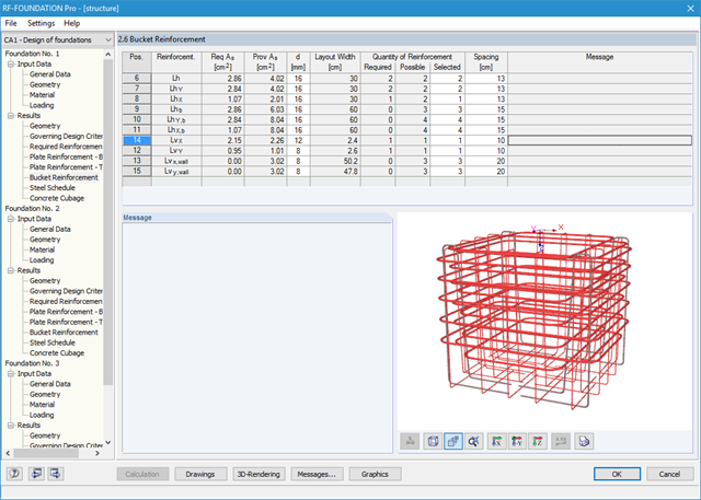
You can display the foundation in excellent rendering quality, including reinforcement. In the rendering, as well as in up to seven different dimensioned reinforcement drawings ready for construction, the module provides a solution proposal for bucket design. It is possible to modify the number, position, diameter, and spacing of used rebars here as well. You can also determine the shape of the applied links.
The dimensions of the foundation plate and bucket can be determined by the add-on module, or can be user-defined. Clearly arranged windows display the results of each performed design, including all intermediate values. They are covered in a reduced printout report providing a verifiable structural analysis.
The deformation analysis with RF-CONCRETE Deflect can be activated in the settings for the analytical serviceability limit state design in the RF-CONCRETE Surfaces module. Consideration of long-term effects (creep and shrinkage) and tension stiffening between cracks can also be managed in the dialog box above. The creep coefficient and shrinkage strain are calculated using the specified input parameters or defined individually.
You can specify the deformation limit value individually for each surface or for an entire surface group. The max. deformation is defined as the allowable limit value. In addition, you have to specify whether the undeformed or the deformed system is to be used for the design check.